Operating Principles of the Three-Phase Asynchronous Motor
Understanding its working principle requires a grasp of electromagnetism, specifically how a stationary set of coils can induce motion in a rotor without any physical electrical connection (brushes). This article details the sequence of operation from the stator input to the mechanical shaft output.
1. Generation of the Rotating Magnetic Field (RMF)
The fundamental prerequisite for the operation of an induction motor is the creation of a Rotating Magnetic Field within the stator.
-
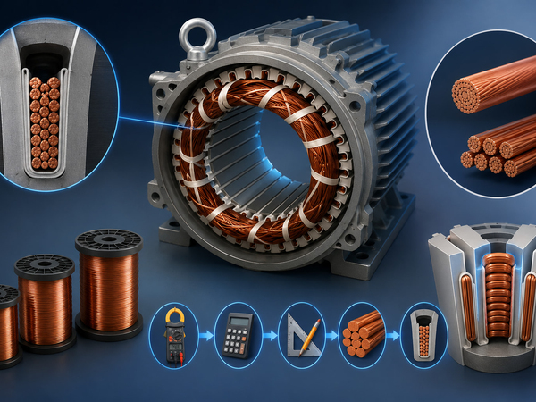
The Setup: The stator carries a three-phase winding, physically displaced by 120^\circ in space.
-
The Input: A three-phase AC supply is applied to these windings. The currents in these phases are also displaced by 120^\circ in time.
-
The Result: According to Tesla's theorem, when balanced three-phase currents flow through these windings, they produce a resultant magnetic flux of constant magnitude. This flux rotates around the stator perimeter at a specific velocity known as Synchronous Speed (N_s).
The synchronous speed is determined by the supply frequency (f) and the number of magnetic poles (P):
N_s = \frac{120 \times f}{P} \quad (RPM)
2. The Induction Process
Once the RMF is established, the energy transfer process begins. This phenomenon relies entirely on Faraday’s Law of Electromagnetic Induction.
-
Flux Cutting: The magnetic flux lines from the stator rotate and "cut" the stationary rotor conductors (bars or windings).
-
Induced EMF: Due to the relative motion between the rotating flux and the stationary rotor, an Electromotive Force (EMF) is induced in the rotor conductors.
-
Closed Circuit Current: Since the rotor conductors are short-circuited (by end rings in a squirrel cage rotor), the induced EMF causes a current to circulate within the rotor bars.
3. Production of Torque and Rotation
At this stage, we have a current-carrying conductor placed within a magnetic field.
-
Lorentz Force: According to the Lorentz force law, the interaction between the stator's magnetic field and the rotor's induced current generates a mechanical force on the rotor conductors.
-
Lenz's Law: The direction of the induced current (and the resulting force) opposes the cause that produced it. The "cause" is the relative speed between the RMF and the rotor.
-
Result: To reduce this relative speed, the rotor starts rotating in the same direction as the stator's Rotating Magnetic Field.
4. The Concept of "Slip"
This is the defining characteristic of an "Asynchronous" motor. The rotor speed (N_r) can never technically equal the synchronous speed (N_s).
Why?
If the rotor were to run at synchronous speed (N_r = N_s), the relative speed would be zero. The stator flux would no longer "cut" the rotor bars, meaning zero induced EMF, zero current, and consequently, zero torque. Friction and load would immediately slow the rotor down.
Therefore, the rotor always lags slightly behind the magnetic field. This difference is called Slip (s):
s = \frac{N_s - N_r}{N_s} \times 100\%
In standard operation, slip typically ranges from 1% to 5% depending on the mechanical load applied to the shaft.
5. Reversing the Direction of Rotation
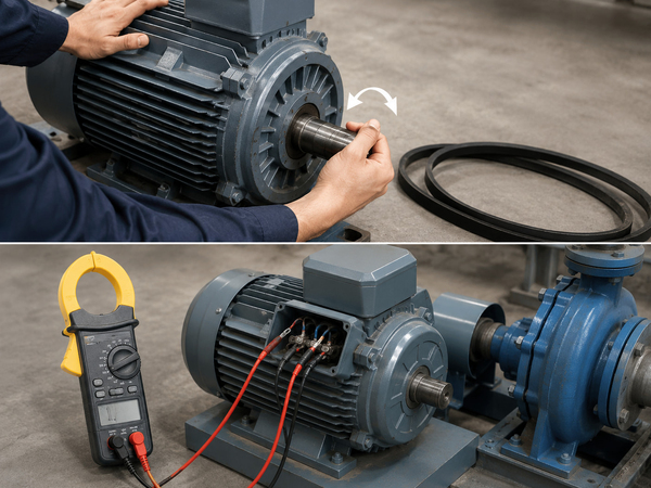
The direction of the motor's rotation is dictated entirely by the direction of the Rotating Magnetic Field. To reverse the motor, one must reverse the sequence of the RMF.
This is achieved simply by swapping any two of the three supply leads (e.g., swapping Phase L1 and Phase L2). This changes the phase sequence (from A-B-C to A-C-B), causing the magnetic field—and thus the rotor—to spin in the opposite direction.
Conclusion
The Three-Phase Induction Motor operates on the principle of electromagnetic induction, where the stator acts as the primary (input) and the rotor as the secondary (output) of a rotating transformer. Its operation is a self-balancing act: as the load increases, the rotor slows down, slip increases, induced current rises, and more torque is produced to handle the load.
Related Articles
- Wire selection (17/07/2026)
- The method to determine the motor overload (17/07/2026)
- The relationship between temperature and feel (11/07/2026)
- Why Not Start Three Phase Asynchronous Motor (11/07/2026)
- Motor with load runtime reasons for the slow speed (30/06/2026)